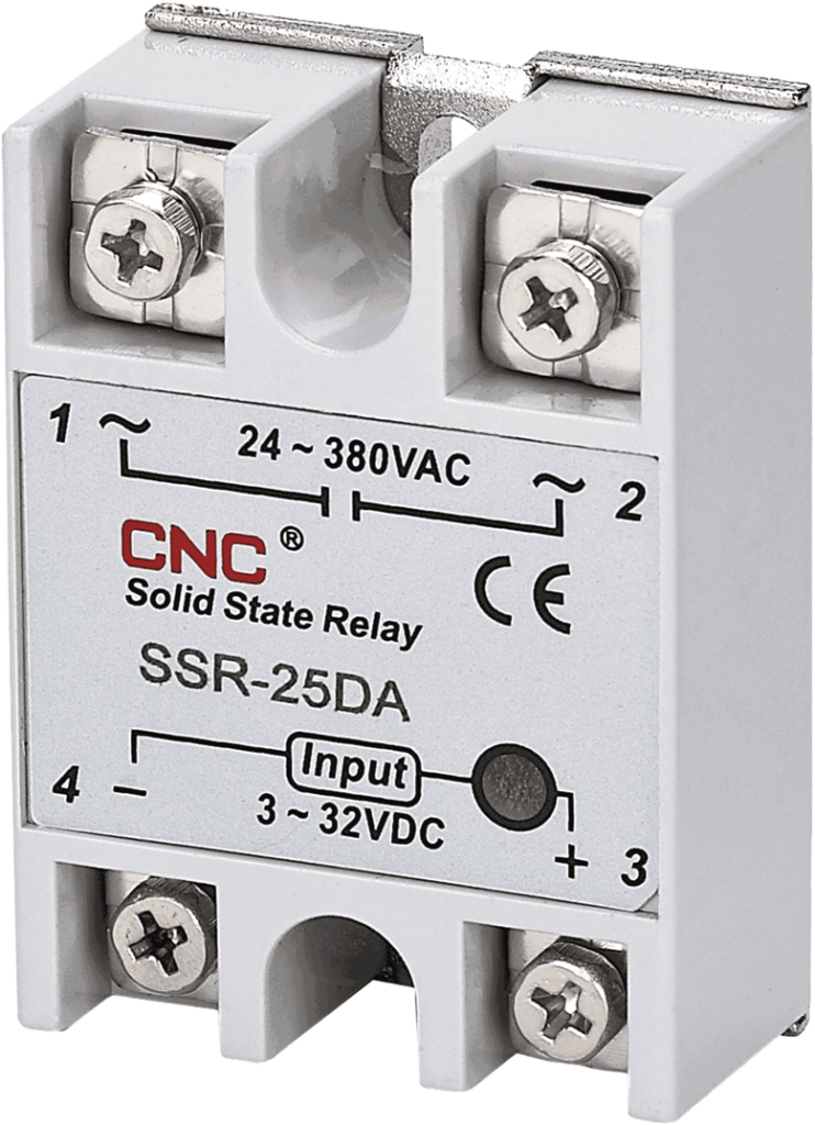
What is an SSR ?
A Solid State Relay (SSR) is an electronic switching device that allows you to control high voltage loads with low voltage signals. Unlike traditional electromechanical relays, SSRs have no moving parts, making them faster, more reliable, and longer-lasting. They are commonly used in applications where precise control and rapid switching are required.
Advantages of SSR :
- No Mechanical Wear and Tear: With no moving parts, SSRs have a longer lifespan and are more reliable.
- Silent Operation: SSRs operate silently, unlike the audible clicking of electromechanical relays.
- Fast Switching: SSRs can switch on and off much faster, suitable for applications requiring high-speed switching.
How to Wire an SSR :
Wiring an SSR is straightforward but must be done correctly to ensure safe and efficient operation. Here’s a basic guide:
- Identify Terminals: SSRs typically have four terminals:
- Input terminals (3 and 4) or (- AND + ): For the control signal.
- Output terminals (L1 and T1): For the load connection.
- Connect Control Signal:
- Connect the positive control signal wire to terminal 3 which is also mention as + Terminal.
- Connect the negative control signal wire to terminal 4 which is also mention as – Terminal.
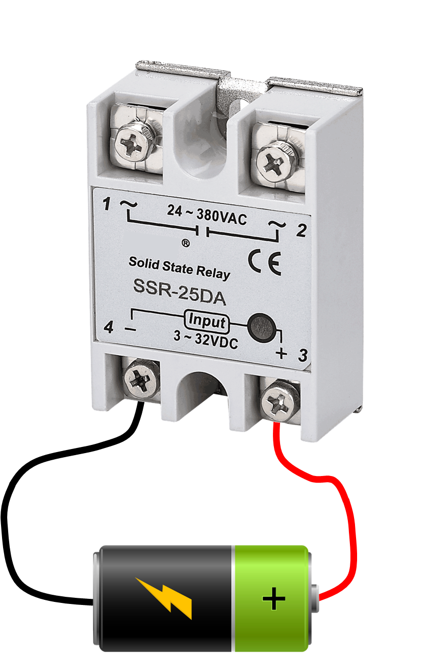
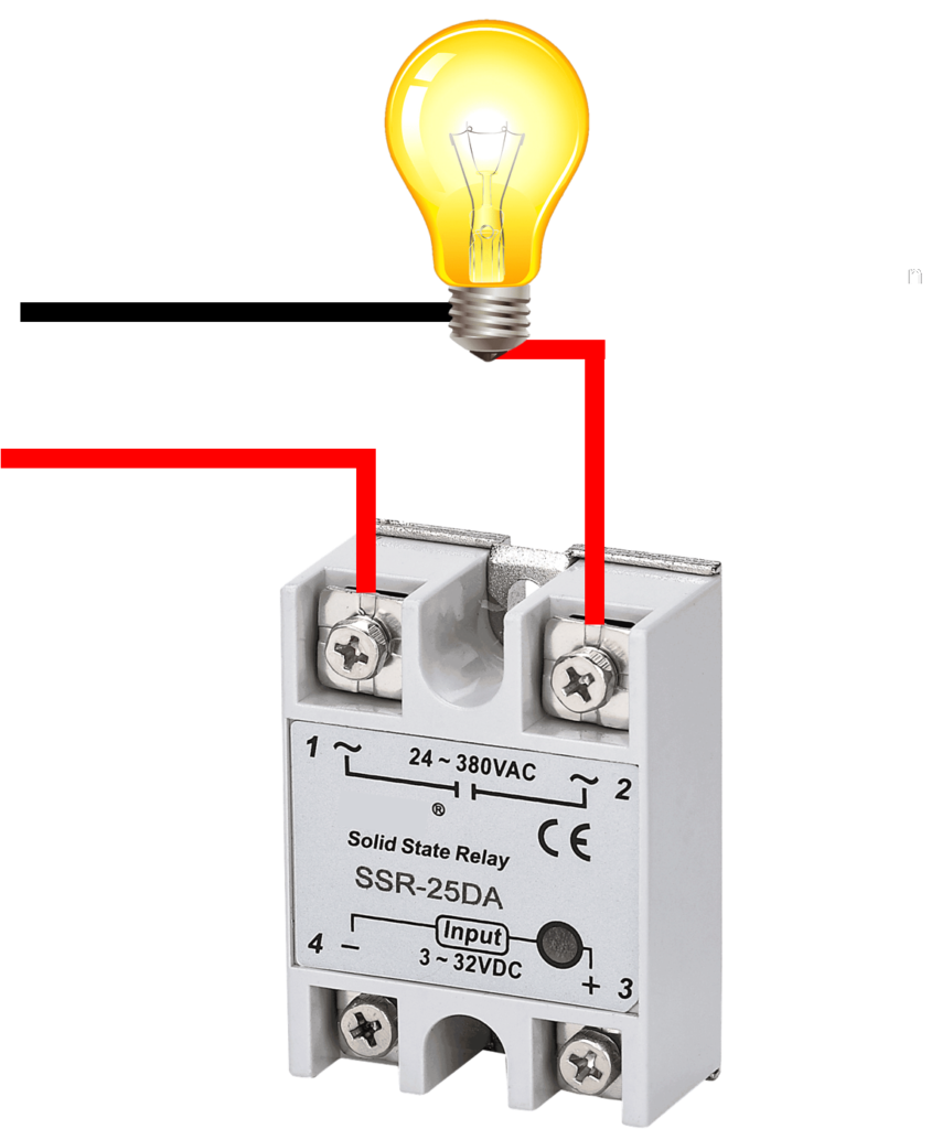
- Connect the Load:
- Connect the AC/DC power supply to terminal L1.
- Connect the load (device to be controlled) to terminal T1
- Ensure Proper Voltage and Current Ratings: Make sure the SSR you are using is rated appropriately for your control signal and load requirements.
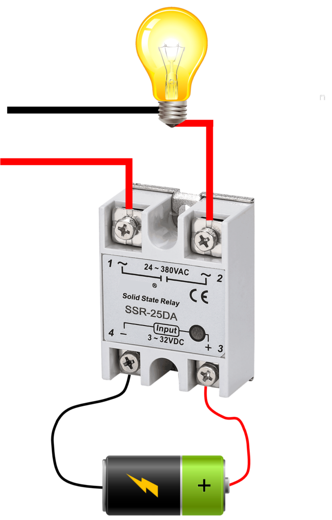
How SSR Turns On and Off
When we apply an input signal to the SSR’s input terminals (3 and 4), it activates the internal LED. This LED emits light that triggers a photodiode or phototransistor inside the SSR. This action then switches on the semiconductor device (like a triac or thyristor) connected to the output terminals (1 and 2), allowing current to flow and powering the connected load.
Similarly, when the input signal is removed, the LED turns off, causing the photodiode/transistor to stop conducting. This action turns off the semiconductor device, stopping the current flow and disconnecting the load from the power supply, thus turning it off.

